
What is Triac
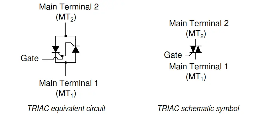
TRIAC is a device that similar to SCR, because of two SCR are connected back to back it consist of a single device with three electrodes but SCR is unidirectional device but TRIAC is Bidirectional device.
SYMBOL OF TRIAC
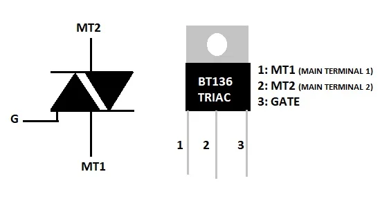
- TRIAC with three terminals MT1 ,MT2 and Gate
- MT1 equal to anode ,MT2 equal to cathode
CONSTRUCTION OF TRIAC
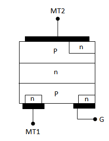
- TRAIC have four layers ,three terminals,six doping area.
- Contact both main terminal of MT1 & MT2 are with P and N as forward and reverse directional bias.
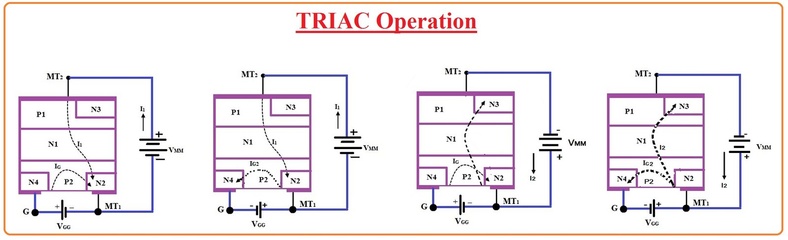
OPERATION OF TRIAC
- Triac operates only in high voltage of power as far it not consist of additional power circuits of ON state
- Alternative current is given directly to device it stands with high power consumption
- Supply to the gate terminal for ON state, if the gate supply either positive and negative supply.
- Triac operate in both forward bias and reverse bias it consist of parallel directional SCR
- Triac device is two directional becomes of two polarities positive & negative it to runs under an four modes of operation
MODES OF OPERTAION
Mode :1
In first MT2 point positive as refer from the MT1 point negative, Gate point also positive as refer from MT1 point negative.

Mode:2
In second MT2 point positive as refer from the MT1 point negative, Gate point negative as refer from MT1 point positive.

Mode:3
In third MT2 point negative as refer from the MT1 point positive, Gate point positive as refer from MT1 point negative.

Mode:4
In first MT2 point negative as refer from the MT1 point positive, Gate point also negative as refer from MT1 point positive.
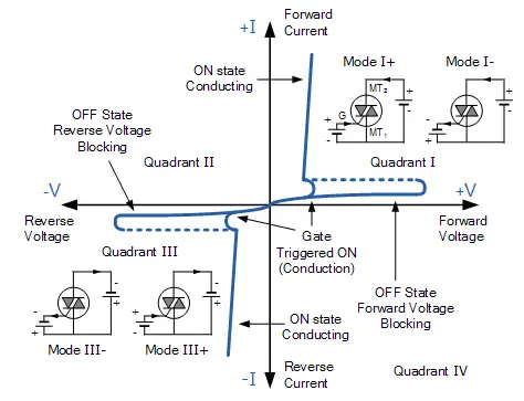
VI characteristics
- The voltage and current in the main terminals as characteristic at quadrant stage
- Triac with the SCR same as forward bias function as far negative bias also conduct at biasing.
- Mode operation function one & three at stage in first quadrant and then second & four at stage in third quadrant.
- The device turning ON stage either as +ve and –ve voltage to gate point.
- Gate point current refer as break over voltage only at higher gate voltage at point of peak level in graph.
Parameters of TRIAC
| Parameter | Typical value | Unit |
| threshold current for | 5-50 | mA |
| Repetitive peak off-state forward voltage | 600-800 | V |
| peak off-state forward voltage repetitive | 600-800 | V |
| RMS on-state current | 4-40 | A |
| Instantaneous on-state voltage | 1.5 | V |
| On-state current | 25 | A |
| Holding current IH | 75 | mA |
| Average triggering current IG | 5 | mA |
TRIAC Triggering
| Triggering mode | Polarity (with respect to MT1) | |
| MT2 | Gate | |
| Mode 1 | Positive | Positive |
| Mode 2 | Negative | Negative |
| Mode 3 | Positive | Negative |
| Mode 4 | Negative | Positive |
Triac phase controller
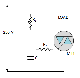
The input of positive and negative half cycles to control the average output power of a.c by load.
The gate control by variable phase angle the phase shift values between degree of 0 to 90. To adjust the variac resistance to get various output through load and act as bidirectional switch.
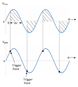
For resistive load

It waveform depends upon the relationship between Ø & α.
Case 1:
α = Ø (lagging waveform)
Case 2:
(b) α > Ø

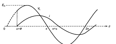
Analysis of regulator
Averages values of load voltage and current are both zero, since the waveforms are symmetrical with equal areas above and below the zero voltage axis
The rms value,

Triac is equal to two SCRs connected back to back
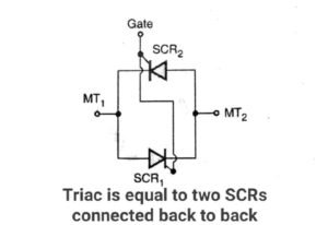
The gate current same. increased IG and corresponding voltage decreased. The triac is differ the SCR gate current only positive but the triac either positive or negative current.
Application of Triac
(i) high power lamp switch
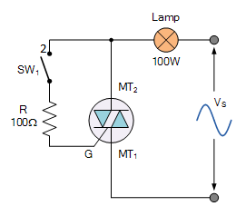
When the switch open there will be no current flow in the circuit. Switch off position current flow to the load or bulb.
(ii) transformer tap change over in electronic circuit
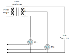
The triac T1, T2 connected transformer secondary. The terminal AC will working the triac T1 conducting , and terminals AB working the triac T2 conduct. BC avoids dangerous short circuit.
Burst – firing controller
The burst firing is also called “ ON – OFF control” . it control the input supply (positive or negative half cycles) the gate pulse on- off circuit in simple form of zero voltage detector.
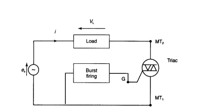
The rms value of current and voltage

APPLICATION OF TRIAC:
- Triac inbuilt in most of Control application such as phase control, speed control, temperature control, liquid level control.
- It used switching device as bi directional functions on/off control function.
- Its also applied regulating alternative current in circuit directly series to load output.
MERITS OF TRIAC
- No parallel diodes for reverse voltage
- Fuse circuit as single only
- Triggering both voltage positive or negative
DEMERITS OF TRIAC
- Low dv/dt rating compare SCR
- Less reliability in circuits
- Switching frequency are less