
What is clipper?
Its wave shaping circuit. The unwanted portion remove the input. The waveform shaped obtained without distorting. It’s a protecting device. Its commonly used transmission purpose.
Types of clipping circuit
1.Series clipper circuits
- Series positive clipper circuit
- Series negative clipper circuit
- Series positive with biasing
- Series negative with biasing
2.Shunt clipper circuit
- Shunt positive clipper circuit
- Shunt negative clipper circuit
- Shunt positive with biasing
- Shunt negative with biasing
a. Series positive clipper circuit
The diode connect the circuit in series. The positive half cycle the diode attain reverse bias and the diode does not conducting.
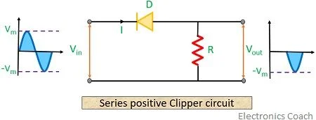
Fig.1. series positive clipper circuit
The negative half cycle diode is forward bias and diode goes conducting stage. so the corresponding output to collect the load resistor.
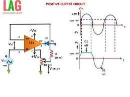
Fig.1.a. series positive clipper circuit using IC 741
b. Series Negative clipper circuit
The diode connect the circuit in series. The positive half cycle the diode is forward bias the diode goes conducting stage. the output voltage waveform collect to load.
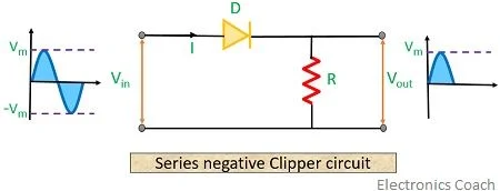
Fig.2 Series negative clipper circuit
The negative half cycle diode is reverse bias and diode does not conducting stage.
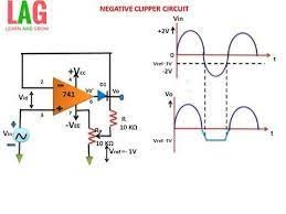
Fig.2.a Series Ngeative clipper circuit using IC 741
c. Series positive clipper circuit bias circuit
Series positive circuit bias circuit an additionally the biasing circuit connected to the across the load. During positive half cycle the diode does not conducting. The biasing circuit connected the forward bias and the diode is conducting state with respect to bias voltage (VB)
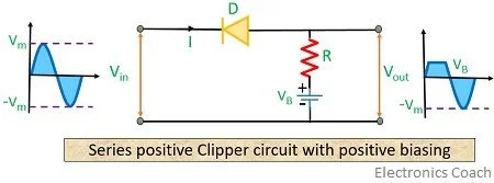
Fig.3.Series positive clipper circuit bias circuit
The negative half cycle operation similar to series positive clipper circuit. The diode forward bias the diode goes to conducting stage and also the corresponding output voltage will appear to the waveform.
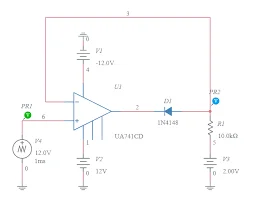
Fig.3.a.Series positive clipper circuit bias circuit using IC 741
d. Series negative clipper circuit bias circuit
The positive half cycle operation similar to series negative clipper circuit. The diode forward bias the diode goes to conducting stage and the corresponding output voltage will appear to the waveform.
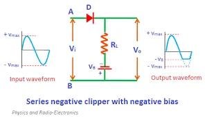
Fig.4. Series negative clipper circuit bias circuit
Series negative circuit bias circuit an additionally the biasing circuit connected to the across the load. During negative half cycle the diode does not conducting. The biasing circuit connected the forward bias and the diode is conducting state with respect to bias voltage (VB).
Fig.4.a Series negative clipper circuit bias circuit using IC741
2. Shunt clippers
In Shut clippers, the diode is connected in parallel with the source.
a. Shunt positive clipper circuit
The shunt positive clipper circuit operation is opposite the series positive clipper. The diode connect the circuit in parallel to load. The positive half cycle the diode is forward bias the output voltage is zero.
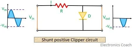
Fig.5.Shunt positive clipper circuit
The negative half cycle diode is reverse bias and diode goes conducting stage. so the corresponding output to collect the load resistor
b. Shunt Negative clipper circuit
The positive half cycle diode is reverse bias and diode goes conducting stage. therefore the corresponding output to collect the load resistor
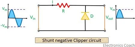
Fig.6.Shunt Negative clipper circuit
The negative half cycle diode is forward bias and diode does not conducting stage. therefore the corresponding output is zero
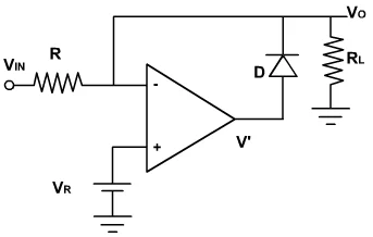
Fig.6.aShunt Negative clipper circuit using IC741
c. Shunt positive clipper bias circuit
The diode and supply voltage connect the circuit in parallel to load. The positive half cycle the diode is forward bias diode does not conduct and this time the supply voltage forward bias connection to the diode the will produce the supply voltage (VB) into the output .
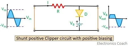
Fig.7.Shunt positive clipper circuit
The negative half cycle diode is reverse bias and diode goes conducting stage. so the corresponding output to collect the load resistor.
d. Shunt Negative clipper bias circuit
The positive half cycle diode is reverse bias and diode goes conducting stage. so the corresponding output to collect the load resistor
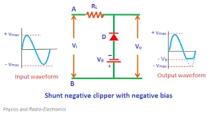
Fig.8.Shunt Negative clipper bias circuit
The diode and supply voltage connect the circuit in parallel to load. The negative half cycle the diode is reverse bias diode does not conduct and this time the supply voltage forward bias connection to the diode the will produce the supply voltage (VB) into the output .
Fig.8.a.Shunt Negative clipper bias circuit using IC741
3. Dual clipper circuit (or) combination circuit with biasing
The combination of circuit it means the series and shunt (or) positive clipper and negative clipper operation performed. So it also called as “Dual clipper”. Both positive and negative cycles are absence in the clipper.
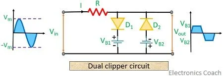
Fig.9.Dual clipper circuit
During positive half cycle the (D1) diode forward biased due to shunt connection the output going to zero. The corresponding supply voltage (VB1) forward biased to the (D1) diode to obtain output voltage (VB1).
During negative half cycle the (D2) diode reverse biased due to shunt connection the output are going to zero. The corresponding supply voltage (VB2) forward biased to the (D2) diode to obtain output voltage (VB2).
Fig.9.a.Dual clipper circuit using IC 741
4.Clipper application
- Transmitters and receivers in televisions
- Noise reduce application
- Power supplies
- Wave generation circuits.