
The UJT SCR Trigger
A SCR Triggering circuit the one of the application of UJT. In this circuit diagram the switch s1 is closed the capacitor c will be charged. In this duration the UJT is off state. When switch s1 is opened immediately the capacitor will be discharged the UJT emitter terminal. Hence the UJT turn on and the SCR can get the gate triggering voltage.
VB1 (off) < (Ig * 1kΩ + Vg)
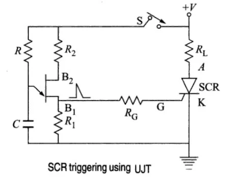
Gate trigger circuit
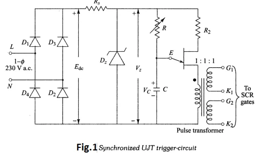
Synchronized UJT – Triggering (Ramp Triggering)
UJT Trigger with SCR
The bridge rectifier rectifies ac to dc, resistance Rs allow the voltage current to zener diode and act as protect the reverse current in the circuit. The variable resistance determined the capacitor charging value when the capacitor discharges the UJT emitter junction is ON condition, the connected pulse transformer induced voltages primary to secondary. The secondary terminal to the input of the SCR gate signal.
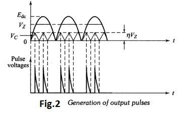
Generation of output pulse
At the end of every half cycle zener diode voltage Vz goes to zero , the synchronization of supply voltage with the trigger circuit across SCRs is achieved. Thus the time t , equal to α/ω , when the pulse is applied to SCR for the first time, will remain constant for the same value of R.