
Parallel connection of MOSFETs
This device is connected in parallel so its increasing forward current carrying capability and its similar to operate a resistance in the on state and has a positive temperature coefficient the term that says in the parallel construction say two power MOSFET if one of them drop large current than the other and its internal temperature will increase, this will increase its on state resistance to automatically reduce the current through it.
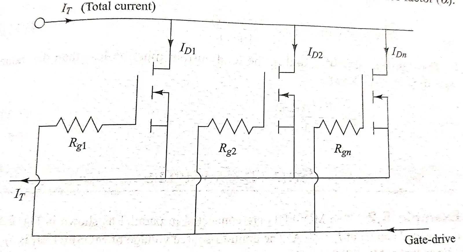
Since although a number of device are connected in parallel for current sharing, fall out of any equipment does not lead to more currents, due to thermal runaway and breakdown of the balance device at the moment the opposite of that encountered in bipolar junction transistor. At that moment the device of power MOSFET it is required to take prevent step to hold the parasitic oscillations as low as possible for connecting resistance in series to MOSFET gate terminals. The gate driving is used to low output impedance of the device and it’s like direct paralleling of power MOSFETs regardless of all the prevent step to taken the select power MOSFETs nearly to all the identical parameters and its same time the equal current sharing will not take place and some of the power MOSFETs will draw more current than the alternative way. The termed called current balance (α).
Unbalance factor (α).
The n number of the power MOSFETs was connected in parallel and the flow of total current IT and the average equal current shared by individual power MOSFETs is denoted ID average .
Therefore,
ID av = IT / n
To calculate the current balance (α) in the worst case condition is consider that is when any one is taking maximum current say IDC(max) , hence the unbalance current factor is,
(α) = ID(max) – ID(av) / ID(av)
(or)
(α) = ID(max) – ID(av) / ID(av) * 100
The current balance (α) is changes between 0 and 1 or between 0 and 100% the (α) value should be 0 the value of (α) is experimentally with increase in the value of (α) and corresponding increased ID(max). but increasing ID(max) the device will get damaged to avoid in this damage the device will operating the rated current. That is
ID(max) ≤ ID (rated)
If (α) is known then care can be taken to limit the total current to a lower value of increase the number of devices n
So ID(max) = ID (rated)
α = ID (rated) – ID (av) / ID (av)
= (ID (rated) / ID (av) ) – 1
But ID (av) = IT / n α = (ID (rated) / IT/n )- 1
= (n. ID (rated) / IT ) – 1
The total current IT = n. ID (rated) / (1 + α )
IT ≤ n. ID (rated) / (1 + α )
Drain Current Calculation
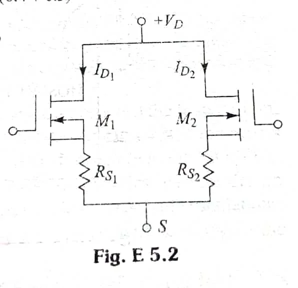
Two MOSFETs are connected in parallel as shown in fig. a carry total current of IT = 30A. the drain to source voltage of MOSFER M1 is VDS1 = 4V and that of MOSFET m2 is VDS2 = 4.5V. compute the drain current of each MOSFET and differences in current sharing if the current sharing series resistances are
(a) RS1 = 0.4Ω and RS2 = 0.3 Ω (b) RS1 = RS2 = 0.7 Ω
Solution
(a) Total current , IT = ID1 + ID2 and VDS1 + ID1 Rs1 = VDS2 + ID2 RS2
Also
Rs2 ID2 = Rs2 (IT – ID1)
VDS1 + ID1 Rs1 = VDS2 + Rs2 (IT – ID1)
Or, VDS2 + ID1 (Rs1 + Rs2) = VDS2 + Rs1 IT
ID1 = VDS2 – VDS1 + Rs2 IT / Rs1 + Rs2
= 4.5 – 4 + 0.3 * 30 / (0.4 + 0.3)
= 13.57 A or 45. 23 %
ID2 = 30 -13.57 = 16.43 or 54.77 %
Since, difference in current sharing,
ΔI = ID2 – ID1
= 16.43 – 13.57 = 2.86A
Or ΔI = 54.77 – 45.23 = 9.54%
b) ID1 = 4.54 -4 + 0.7 * 30 / 0.7 + 0.7
= 15.36 A or 51.2 %
ID2 = 30 -15.6 = 14.64 A or 48.8 %
ΔI = 51.2 – 48.8 = 2.4 %